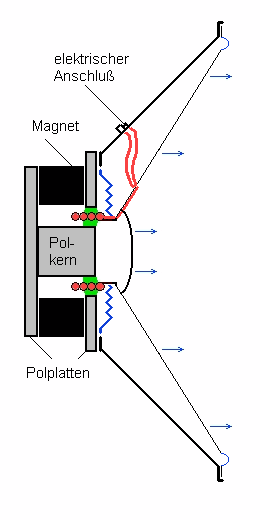
The drawing on the left shows the structure of a driver. It mainly consists
of a diaphragm and a drive system. The drive system consists of a magnet
with the purpose of generating a magnetic filed in the area that is marked
green.
The voice coil (red) - under current - is located in this green marked
area. A force F is generated in the voice coil that is vertical to the
magnetic field and vertical to the direction of the current in the conductor.
The picture shows that
- the magnetic field runs vertical
- the current also runs vertical
- the resulting force is horizontal
What are the variables determining the driver system's behaviour?
a) the strength of the magnetic field and its extension
b) the voice coil's properties
The current running through the voice coil generates a force F, exactly
where the voice coil is suspended in the magnetic field:
| F = (sm * B) *
I, (equation 1) |
Where sm is the length of the conductor within the magnetic field (or
the number of windings x circumference of a winding), B is the strength
of the magnetic field and I is the current.
The expression in brackets is also called electromagnetic force factor
F/I or B*L (where L indicates the length, however, we would like to
use s for length since we need L for inductance).
If current I is applied to a driver, the diaphragm moves with a certain
force F = (sm * B) * I, depending
on the electromagnetic force.
However, what is the value of the current running through the voice
coil? To answer this question we need to introduce further variables.
1. Ohm's law:
This law means that with current I
where UR is the voltage applied to the
driver and R is the ohmic resistance. This is correct when DC is applied
but not for AC.
n the following we'll apply AC; the variables I, U are complex amplitudes.
2. Induced voltage
When the voice coil moves within the magnetic field, a voltage
Ui is induced in the voice coil:
| Ui = (sm
* B) * v, (equation 3) |
where sM is the length of the conductor within the magnetic field,
B is the flux density of the magnet and v is the velocity of the voice
coil.
Therefore, the induced voltage is dependant on the electromagnetic
force factor and the velocity of the voice coil.
3. Voltage on an inductance
When AC is applied, the voice coil - having an inductance - also has
a voltage: UL
| UL = j ω
L * I, (equation 4) |
where j means that UL runs ahead of I by 90 degrees
and ω is the angular frequency, therefore 2 * π * frequency
f.
Equations for the drive system
Thus, it implies for the drive system, where the voltage applied to
the driver Ug consists of individual voltages: Uges
= UR + Ui + UL, values applied individually:
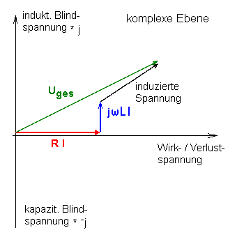
Uges = R * I + (sm
* B) * v + j * ω * L * I, (equation 5)
|
Again, the addends are complex amplitudes, i.e. scalar addition should not take
place.
When voltage is applied to the driver, this voltage is divided into
three different "activities" (please refer to the picture on the left):
a) UR = R * I is turned into heat by the voice coil
b) UL = j * ω * L * I serves for reloading of the voice
coil
c) Ui = sm * B * v corresponds to the movement
of the diaphragm 
The less power in a) is turned into heat, the higher the efficiency
of the driver might be. b) puts power into the driver and out of it
(that's the characteristic of a coil) and c) is responsible for the
drive; this electrical energy is tuned into mechanical energy.
Considering a coil with infinite low resistance (superconductor), having
hardly any inductance, only part c) would be effective. That implies
that:
sm * B * v = Ui
(equation 6), |
whereby the phase of diaphragm movement and voltage would be shifted by exactly
90 degrees, since the velocity is highest in zero crossing of the diaphragm,
or when the voltage has just reached its maximum value.
It's not easy to work with equations and, moreover, the sound transition
from the diaphragm to the ambient air also plays a role, Thiele and
Small developed their model to determine the low frequency properties
with the following parameters:
- total Q factor Qts
- resonance frequency f0 (or fe)
- equivalent volume of compliance VAS. To calculate these
parameters, several programmes are available free of charge on our tools
page.
|